
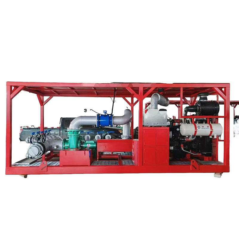
A cementing pump regulates three linked variables on every job: discharge pressure against formation and casing limits, slurry density delivered to the wellhead, and displacement rate that keeps the leading edge of cement where the program places it. Unlike fracturing fleets chasing peak stage horsepower, cementing units meter weighted slurry through narrow pressure windows for hours with minimal density drift. This guide explains how cement slurry pumps achieve that control, what skid instrumentation provides, and how pressure and displacement specs differ from frac pump duty.
What Do Cementing Pumps Control During a Job?
Cementing pumps move blended cement slurry from bulk tanks or mixers through treating lines to the wellhead while the control system tracks discharge pressure, flow rate, and calculated density. Pressure must stay below fracture gradient and casing burst margins yet high enough to overcome friction in the annulus or liner lap. Rate must match the displacement schedule so spacers, cement, and displacement fluid arrive in sequence without u-tubing or channeling.
Density control is not a separate device—it emerges from mix-water ratio, additive concentration, and consistent pump delivery. A well cementing pump that surges rate or loses suction integrity will show density variation at the head even when lab slurry tests pass. Reciprocating plunger cementing units remain common because they hold stable rate across changing back-pressure on weighted slurry.
Modern cementing skids integrate density meters, magnetic flow elements, and pressure transducers upstream and downstream of the pump so the operator can trim mix rate and pump speed together.
How Are Cementing Pump Pressure Windows Defined?
Completion and cementing engineers publish maximum allowable surface pressure, equivalent circulating density limits, and sometimes minimum rate to prevent static gelation in the line. The cementing pump operates inside that envelope for the entire displacement—not a short peak like a fracturing stage.
Back-pressure rises as slurry enters a restricted annulus or as displacement fluid pushes the column deeper. Plunger pumps respond to increased resistance by slowing effective rate unless speed is adjusted; VFD-driven units trim RPM to hold setpoint pressure when the program switches to pressure control mode.
Over-pressure risks formation breakdown or casing failure; under-pressure risks incomplete placement or free-fall segregation in deviated holes. RFQs should state fracture gradient, casing test pressure, and whether the unit must hold pressure during shut-in periods between batches.
- Surface pressure limited by casing design and formation fracture gradient
- Sustained duty—not intermittent peak treating like fracturing
- Pressure control mode may override rate setpoint during critical displacement
How Do Cement Slurry Pumps Manage Density and Displacement?
Slurry density targets—typically expressed in pounds per gallon or kilograms per cubic meter—depend on blend design, mix-water salinity, and additive loading. The pump delivers what the mixer produces; consistent suction supply and stable strokes per minute keep the density trace flat on the job log.
Displacement rate is programmed in barrels or cubic meters per minute relative to hole volume and cement volume calculated for the annular or liner section. Too fast can erode weak formations or cause lost circulation; too slow allows slurry to thicken in the line. Cementing pump displacement control therefore pairs mechanical rate stability with real-time density feedback from the mixing system.
Batch mixing and continuous mixing skids place different demands on the pump: batch systems pulse as tubs empty; continuous systems need steady suction from an active mixer. Specify which mixing philosophy the pump must support when comparing quotes.
What Instrumentation and Skid Packages Support Control?
Land and offshore cementing units mount triplex plunger pumps on skids with manifolds, relief valves, and data acquisition tied to the cementing control cabin. Density, rate, and pressure trend on one screen so the operator can correlate pump speed with mix trim.
Relief and recirculation paths protect the fluid end when a line plugs or a valve closes unexpectedly—critical on weighted slurry where dead-head pressure spikes quickly. Skid packages may include multiple pumps in parallel for high-rate primary cementing or a single unit for liner and remedial jobs.
High-pressure plunger pump series frames adapted for cementing share power-end reliability with other well service builds while using fluid ends rated for abrasive cement and spacer fluids.
How Do Cementing Pumps Differ from Fracturing Pumps on Pressure and Slurry?
Fracturing pumps deliver proppant slurry at high rate during short stages where peak treating pressure and horsepower dominate economics. Cementing pumps prioritize density accuracy, sustained displacement, and pressure staying inside a narrow window for much longer intervals on weighted cement—not proppant schedules.
Both may use triplex or quintuplex plunger wet ends, but cementing fluid ends emphasize consistent metering on thick slurry with less extreme solids loading than frac sand stages. Fracturing units are sized for parallel peak horsepower; cementing units are sized for controllable rate and reliable suction on mix systems.
Using a fracturing pump specification on a primary cement job without re-evaluating density control and sustained pressure hold can oversize peak capability while underspecifying mix-line integration and slow-rate stability.
Specifying JET Packages for Cementing Pressure and Slurry Control
Provide job type (surface, intermediate, liner, remedial), target slurry density range, displacement rate, maximum surface pressure, and mixing system layout (batch or continuous).
Review the high-pressure plunger pump series for reciprocating frames suitable for cementing skid integration, and note if your program requires pressure-control override or dual-pump parallel layout.
Request a quote through the contact page with well depth, casing program summary, and destination so engineering can align fluid end, relief strategy, and rate turndown with your cementing program.
FAQ
What is the difference between a cementing pump and a fracturing pump?+
Cementing pumps meter weighted cement slurry through sustained displacement with tight density and pressure control over long job intervals. Fracturing pumps deliver proppant slurry at high rate during short stimulation stages where peak treating pressure and fleet horsepower matter most. Fluid end design and control priorities differ even when both use plunger architecture.
How is cement slurry density controlled at the pump?+
Density is set at the mixer through water–cement ratio and additives; the pump maintains stable rate and suction so that slurry arrives at the wellhead without surging. Instrumentation on modern skids correlates pump speed with density readings to trim the blend in real time.
Why are plunger pumps common for well cementing?+
Reciprocating plunger units hold predictable displacement per stroke and tolerate high discharge pressure on weighted slurry. That stability helps match displacement schedules and respond to changing annular back-pressure without the curve limitations centrifugal pumps face on thick fluids.
Does JET supply pumps for cementing skid packages?+
JET builds high-pressure reciprocating plunger packages suitable for cementing and well service skids. Share slurry density range, rate, pressure limits, and mixing system type when requesting a proposal.